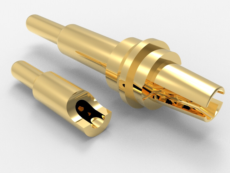
Contact Resistance Severely Affect Pogo Pin Performance. Discover How it Ruins Top Performance, Find Solutions to Optimize Your Connections
Introduction
In electronic device design, Pogo Pins play a crucial role. Their performance directly impacts the device’s reliability and efficiency. However, contact resistance, a small but significant factor, often gets overlooked. Contact resistance can degrade signal quality and cause stability and performance issues in devices.
This article explores the causes and effects of contact resistance and how to optimize Pogo Pin performance to ensure top performance under high-load conditions.
2. What is Pogo Pin Contact Resistance?
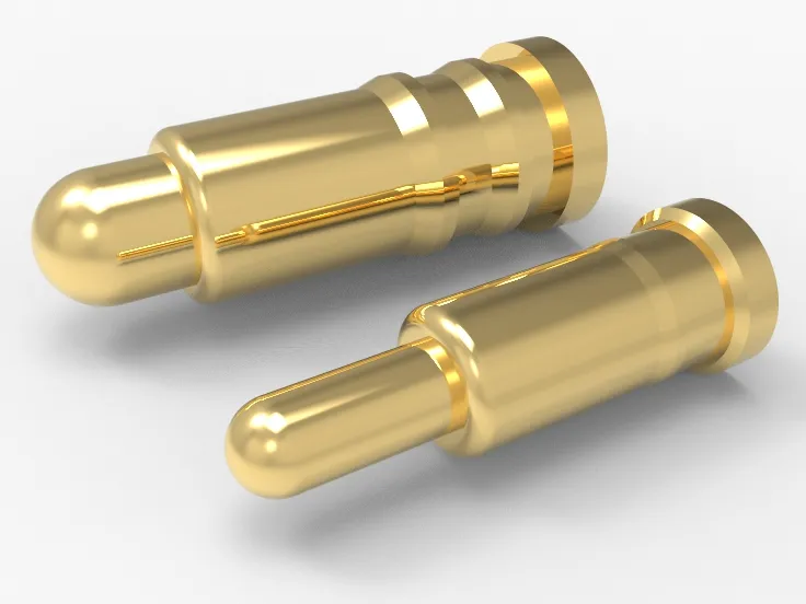
- Pogo Pin contact resistance is the resistance encountered when current flows through the contact point of a Pogo Pin. It consists of contact resistance and contact voltage drop. Contact resistance arises from poor contact or insufficient contact area, while contact voltage drop results in voltage reduction across the circuit, potentially causing device malfunctions and performance issues.
- Pogo Pin contact resistance affects device stability and transmission efficiency. Measures such as improving contact surface treatment, increasing contact area, and choosing suitable materials and designs can help reduce contact resistance, enhancing Pogo Pin performance for reliable device operation.
3. Impact of Contact Resistance on Device Performance
3.1 Obstacles in Current Transmission
High contact resistance can significantly impair current transmission:
- Energy Loss: Increased contact resistance causes higher voltage drops at contact points, leading to energy loss and reduced efficiency.
- Signal Quality: In high-frequency or high-speed data applications, high contact resistance can degrade signal quality, affecting performance and stability.
- Heat and Energy Consumption: Higher contact resistance generates more heat, potentially causing local overheating and increased overall energy consumption.
- Shortened Device Lifespan: Prolonged high contact resistance can cause contact points to loosen or wear out, shortening device’s lifespan.
To mitigate these issues, engineers often optimize contact materials, surface treatments, contact area, pressure, and operating conditions to maintain efficient, stable, and reliable performance.
3.2 Reduced Device Stability and Reliability
Increased contact resistance impacts the stability and reliability of devices using Pogo Pins:
- Unstable Current Transmission: High contact resistance creates resistance to current flow, leading to signal attenuation or instability.
- Signal Degradation: Increased contact resistance can cause signal distortion or attenuation, affecting data accuracy and reliability.
- Increased Heat: High contact resistance generates more heat, potentially raising device temperature and affecting long-term stability and lifespan.
- Increased Mechanical Wear: Higher contact resistance can lead to more wear on the Pogo Pins’ spring material or contact surfaces, reducing lifespan and reliability.
To reduce the impact of contact resistance:
- Use High-Quality Pogo Pins: Quality materials and manufacturing reduce contact resistance and improve efficiency.
- Regular Cleaning and Maintenance: Clean Pogo Pins and contact surfaces to minimize oxidation and contamination.
- Optimize Design: Arrange Pogo Pins to avoid bending or stretching, reducing contact resistance.
These measures can effectively mitigate the negative effects of contact resistance, enhancing overall performance and lifespan.
3.3 Potential Heating and Power Consumption Issues
Contact resistance in Pogo Pins can lead to heating and power consumption problems. When Pogo Pins are used, their contact resistance generates a small amount of heat due to resistance at the contact surface. Though the heat from each pin is minimal, it can accumulate in large-scale applications, potentially raising the overall temperature of the device. Key factors affecting heating from contact resistance include:
- Current Size and Frequency: Higher current or frequency increases energy loss and heat.
- Contact Resistance Size: Larger resistance generates more heat, so minimizing it is crucial.
- Materials and Design: Choosing the right materials and design can reduce heat generation.
- Heat Dissipation and Temperature Control: Effective heat dissipation and temperature control measures are necessary to manage heat buildup.
Even though individual Pogo Pins produce minimal heat, managing contact resistance-related heating is vital for device stability and reliability in large-scale and high-frequency uses.
4. Testing and Evaluating Pogo Pin Contact Resistance
4.1 Testing Methods
To test Pogo Pin contact resistance:
4.1.1 Prepare Testing Equipment: Use accurate digital meters or specialized resistance testers.
4.1.2 Choose a Method: The four-wire method (Kelvin test) is preferred for precision, avoiding lead resistance interference.
4.1.3 Testing Steps:
- Connect Pogo Pin to the testing device.
- Set the device to resistance testing mode and configure parameters (current, range).
- Perform multiple measurements and average the results.
- Analyze data for contact resistance size and stability.
4.1.4 Considerations:
- Environmental Conditions: Test in consistent conditions to avoid temperature and humidity effects.
- Pressure and Usage Conditions: Account for real-world pressure and usage, which can affect resistance stability.
4.1.5 Results Analysis and Application:
- Based on the test results, assess if the Pogo Pin meets design requirements and make necessary adjustments and improvements.
The detailed testing and evaluation process helps effectively manage contact resistance in Pogo Pins, ensuring their reliability and stability in device applications.
4.2 Comparing Testing Methods
4.2.1 Four-Wire Method:
- Description: Uses four probes—two for current and two for voltage—eliminating lead resistance.
- Pros: Accurate, no lead interference.
- Cons: Complex, costly, and not suitable for quick field tests.
4.2.2 Two-Wire Method:
- Description: Measures resistance with two wires—one for current and one for voltage.
- Pros: Simple, quick.
- Cons: Less accurate, lead resistance affects results, especially for low resistance.
4.2.3 Micro-Ohmmeter Method:
- Description: Uses a micro-ohmmeter for direct measurement.
- Pros: High accuracy, can measure very low resistance.
- Cons: Expensive, requires skill, not ideal for quick field tests.
4.2.4 Automated Testing System:
- Description: Automates large-scale resistance testing by controlling current and measuring voltage.
- Pros: Efficient, precise for mass production.
- Cons: High initial cost, not suited for small-scale or R&D.
Decide on the method according to your particular needs, financial limits, accuracy demands, and testing environment.
5. Methods to Address High Contact Resistance
5.1 Choosing the Right Materials and Coatings
High contact resistance often stems from poor material choice or coating quality on Pogo Pins. Here’s how to address it:
5.1.1 Select Appropriate Materials:
- Conductive Materials: Use conductive metals like brass or stainless steel for Pogo Pin contacts. Opt for materials with excellent and stable conductivity to minimize resistance.
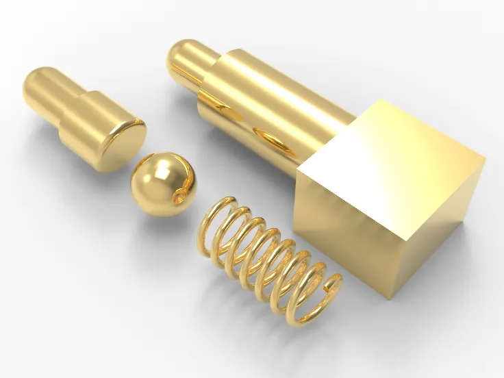
- Elastic Materials: Use spring steel or other high-elasticity materials for the spring parts to ensure they maintain elasticity and stable contact over time.
5.1.2 Apply Quality Coatings:
- Metal Coatings: Use high-quality coatings such as gold or nickel to enhance conductivity and corrosion resistance.
- Surface Treatment: Apply suitable surface treatments like plating or chemical deposition to improve surface smoothness and conductivity.
5.1.3 Prevent Contamination and Oxidation:
- Regular Cleaning: Keep Pogo Pin contacts clean to avoid dust and oil that can affect resistance.
- Prevent Oxidation: Store Pogo Pins in a dry, non-oxidizing environment or use anti-oxidation coatings to extend their lifespan.
5.1.4 Testing and Quality Control:
- Strict Testing Standards: Implement rigorous contact resistance tests during production to ensure each Pogo Pin meets design specifications.
- Quality Control: Establish a robust quality control system to monitor resistance trends and adjust production methods and materials as needed.
Choosing the right materials and coatings, along with enhanced quality control and maintenance, can effectively solve high contact resistance issues and ensure reliable performance across applications.
5.2 Design Optimization and Manufacturing Improvements
Addressing high contact resistance involves optimizing design and improving manufacturing techniques:
5.1. Design Optimization:
- Contact Point Design: Improve the geometry and size of contact points to maximize contact area and pressure, thus reducing resistance.
- Spring Design: Design springs to maintain stable elasticity and conductivity over long-term use.
- Guidance Structure: Optimize the guidance structure for precise and quick alignment during connection to reduce resistance fluctuations.
5.2. Manufacturing Improvements:
- Precision Machining: Use high-precision techniques like CNC machining to ensure accurate contact points and smooth surfaces.
- Automation: Implement automated production lines to boost efficiency and consistency, reducing human factors affecting resistance.
- Quality Inspection: Employ advanced inspection technologies, such as optical and scanning electron microscopes, to assess surface quality and geometry.
5.3. Material Selection and Processing:
- Conductive Materials: Choose high-purity copper or copper alloys for stable, low resistance.
- Surface Coatings: Apply top-notch coatings such as gold or nickel to boost conductivity and resist corrosion.
5.4. Reliability Testing and Validation:
- Long-Term Stability Testing: Conduct extended resistance tests to simulate real-world performance.
- Environmental Testing: Test under various conditions (high/low temperatures, humidity) to evaluate resistance changes.
- Optimizing design and manufacturing processes can significantly improve Pogo Pin performance, ensuring stable and reliable operation across various applications.
6. Case Study Analysis
6.1 Cases of Performance Decline Due to High Contact Resistance
- In Electronic Devices: Devices like smartphones and tablets may experience increased contact resistance in connectors or sockets over time or due to environmental factors. This can lead to slower charging speeds, unstable data transfer, or charging failures.
- In Automotive Electronics: High contact resistance in automotive ECUs and sensor connections can cause error codes, affecting engine performance or vehicle stability and safety.
- In Industrial Control Systems: In automation and control systems, such as PLCs and sensors, high contact resistance can lead to unstable signal transmission or data loss, impacting production efficiency and equipment stability.
6.2 How to Address These Issues Through Design and Material Improvements
6.2.1 Design Optimization:
- Increase Contact Area: Use larger pins or socket designs to reduce contact resistance.
- Optimize Contact Force: Enhance contact force in connectors or sockets to ensure stable connections and reduce resistance changes.
6.2.2 Material Selection:
- High-Conductivity Materials: Choose metals like copper or silver for connectors or sockets to lower resistance.
- Corrosion-Resistant Materials: Use materials that withstand moisture or corrosive environments to ensure stable contact over time.
6.2.3 Surface Treatment:
- Conductive Coatings: Apply coatings like silver or gold to improve conductivity and reduce resistance.
- Anti-Oxidation Treatment: Treat metal surfaces to prevent oxidation, extend lifespan, and maintain stable performance.
6.2.4 Sealing and Protection:
- Dust and Water Resistance: Design connectors or sockets with protective casings to prevent dust, moisture, or contaminants from affecting performance.
6.2.5 Regular Maintenance:
- Cleaning and Inspection: Regularly clean and inspect connectors or sockets, especially in polluted or harsh environments, to ensure good contact performance.
These measures help effectively reduce performance issues caused by high contact resistance, improving the reliability and stability of devices through design, material choices, and maintenance.
7. Conclusion
This blog details the impact of contact resistance on Pogo Pin performance and emphasizes that optimizing design and material choices can address this issue, enhancing device performance and reliability. For additional details or technical help, reach out to our CFT team.


