Skip to content
 How to Calculate Spring Force for Pogo Pins Accurately. Explore the Impact on Precision and Stability to Ensure Pogo Pin Reliable Connections
1. Introduction: How to Calculate Spring Force?
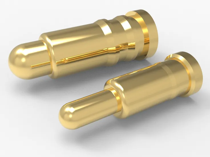
Pogo Pins are widely used in electronic design and manufacturing for connections and testing. Calculating the spring force accurately is crucial for product performance and reliability. How can we precisely calculate the spring force of Pogo Pins and ensure its accuracy in practical applications?
This article will explain the key steps and methods for calculating spring pin force, as well as effective measures to ensure accuracy. It aims to help you master this essential technique for more efficient and stable connections and testing.

2. Basic Concepts of Spring Force, how to Calculate Spring Force?
2.1. Basic Concept of Pogo Pin Spring Force
Pogo Pins are common components in electronic connectors used for testing probes and connectors. Understanding the basic concept of spring force is vital for working with Pogo Pins. Spring force is the restoring force caused by the deformation of the spring, following Hooke’s Law, which is given by:
F=−k⋅x
Where:
- F is the spring force (in Newtons, N),
- The value ‘k’ represents the spring’s stiffness, expressed in Newtons per meter (N/m),
- The ‘x’ value represents how much the spring is compressed or stretched, measured in meters.
Hooke’s Law says that the force of the spring depends on how much it’s stretched or compressed, and it pushes back against the direction of that change. For Pogo Pins, the spring constant k determines the spring’s stiffness, and x is the length the Pogo Pin compresses during use.
2.2 Key Points in Practical Applications
2.2.1 Determining the Spring Constant k:
- The spring constant is determined by how stretchy the material is and the shape of the spring. Johoty usually provides standard spring constants, and clients can select the appropriate Pogo Pin based on their needs.
2.2.2 Controlling Deformation x:
- In practice, the compression of the Pogo Pin needs to be precisely controlled to ensure the spring force is within the design range. This involves design tolerances and assembly precision.
2.2.3 Example Calculation of Spring Force:
Understanding spring force calculations helps us apply Hooke’s Law to real problems. Here are some simple examples:
2.2.3.1: Basic Calculation
Problem: A spring with a stiffness of 200 N/m is stretched by 0.05 m. Calculate the spring force.
Solution: Using Hooke’s Law F=−k⋅x:
- k=200 N/m
- x=0.05 m
Calculate: F=−200×0.05=−10 N
The spring force is −10 N. The negative sign means the force is pushing back against the spring’s stretch.
2.2.3.2: Finding the Spring Constant
Problem: A spring compressed by 0.02 m exerts a force of 15 N. Find the spring constant.
Solution: Rearranging Hooke’s Law k=−F/x:
- F=15 N
- x=0.02 m
Calculate: k=15/0.02=750 N/m
The spring constant is 750 N/m.
2.2.3.3: Spring Deformation Under Different Loads
Problem: A spring with a constant of 1000 N/m needs to handle loads of 5 N, 15 N, and 25 N. Calculate the deformation for each load.
Solution: Using x=F/k:
- For F=5 N, x=5/1000=0.005 m
- For F=15 N, x=15/1000=0.015 m
- For F=25 N, x=25/1000=0.025 m
Deformations are 0.005 m, 0.015 m and 0.025 m.
2.2.3.4: Design Requirement
Problem: Design a spring to produce a force of 30 N with a maximum deformation of 0.1 m. Find the required spring constant.
Solution: Using k=F/x :
- F=30 N
- x=0.1 m
Calculate: k=30/0.1=300 N/m
The required spring constant is 300 N/m.
These examples show how to use Hooke’s Law for spring force calculations, useful for engineering and design.
By understanding these basic concepts and applying the formulas, designers can effectively predict and control the performance of Pogo Pins in practical applications, ensuring reliable and accurate connections and testing.

2.3 The Significance of Spring Constant (k) and Its Effect on Spring Force
When discussing Pogo Pins, the spring constant (k) is crucial. It determines the pin’s stiffness and force. Understanding how the spring constant affects spring force helps in designing and selecting the right Pogo Pin for various applications.
2.3.1 Definition of Spring Constant (k)
- The spring constant, also known as the stiffness coefficient, shows how much force a spring exerts per unit displacement. It’s measured in Newtons per meter (N/m). If the spring constant is larger, the spring is stiffer and you need to apply more force to compress or stretch it by the same distance.
2.3.2 Calculating Spring Constant
The spring constant depends on the material and the spring’s dimensions:
- Material’s Elastic Modulus: Higher modulus means a higher spring constant.
- Spring Diameter: Larger diameter increases the spring constant.
- Number of Coils: Adding more coils to a spring lowers its spring constant.
2.3.3 When choosing Pogo Pins, consider:
- Application Scenario: Different scenarios require different spring forces. Test probes may need less force, while connectors may need more for reliable contact.
- Durability: A higher spring constant can mean more stress, so balance spring force with the lifespan of the pin.
- Tolerance and Precision: Ensure accurate control of compression displacement during assembly.
Understanding and calculating the spring constant helps in selecting and applying Pogo Pins to meet specific needs and ensure the performance and reliability of electronic products.
3. Factors Affecting Spring Force, how to Calculate Spring Force?
The spring force of Pogo Pins is crucial for connection performance. Key factors affecting this force include:
- Material Choice: Pogo Pins use high-strength spring steel or stainless steel. These materials offer good elasticity and durability, maintaining stable spring force through repeated compression and release. The material’s mechanical properties and surface treatment also impact force stability.
- Spring Design: The design parameters, like wire diameter, number of coils, free length, and compression length, significantly affect the spring’s performance. Larger wire diameter and more coils generally increase spring force but also stiffness. Designers must balance force and elasticity based on application needs.
- Manufacturing Process: The forming and heat treatment processes affect the spring’s dimensions and performance consistency. Precise forming ensures uniformity, while proper heat treatment enhances elasticity and reduces fatigue failure risk.
- Coating: Coatings like gold, silver, or nickel improve conductivity and corrosion resistance. The coating’s uniformity and thickness impact contact resistance and force stability. High-quality coatings ensure reliable contact and minimize wear and corrosion.
- Operating Environment: Temperature, humidity, and chemical exposure can affect spring force. Extreme temperatures may alter material properties, while high humidity or corrosive environments can damage coatings and reduce force.
- Usage Frequency: Frequent compression and release can lead to material fatigue, decreasing spring force. Design should account for fatigue life to ensure long-term reliability, choosing suitable materials and processes.
- Compression Amount: The amount of compression affects spring force. Excessive compression can cause permanent deformation, reducing force, while insufficient compression might not provide adequate pressure, affecting connection stability. Proper compression design is key to stable spring force.
Considering these factors ensures Pogo Pins meet application needs and deliver reliable electrical connections.
4. Spring Force Testing and Validation, how to Calculate Spring Force?
The spring force of Pogo Pins affects connection stability and reliability. To ensure Pogo Pins perform well, thorough testing and validation are needed:
4. 1. Testing Equipment and Tools
- Mechanical Test Machine: Use precise machines like a universal test machine to measure the spring force. These machines provide accurate force-displacement curves for analyzing the spring’s performance.
- Displacement Sensor: High-precision sensors record displacement changes under compression, ensuring accurate results.
- Environmental Chamber: Simulate real conditions by testing Pogo Pins under various temperatures and humidity levels.
4. 2. Testing Procedure
Initial Force Test:
- Sample Preparation: Prepare several Pogo Pins samples for consistency and representativeness.
- Sample Installation: Secure the samples in the mechanical test machine.
- Initial Force Measurement: Compress the Pogo Pins at a constant rate and record the initial compression force. Ensure the compression falls within the design range (e.g., 1.5mm).
Force-Displacement Curve Test:
- Loading Process: Set different compression levels on the test machine, record force values, and generate force-displacement curves.
- Curve Analysis: Assess linear and nonlinear regions to evaluate the spring’s elasticity and plastic deformation characteristics.
Fatigue Test:
- Cycle Loading: Perform high-frequency cycle loading to simulate repeated compression and release.
- Force Variation: Record force changes after a set number of cycles (e.g., 10,000 or 50,000) to assess fatigue life and force degradation.
Environmental Impact Test:
- Temperature Test: Test spring force at high (e.g., 85°C) and low temperatures (e.g., -40°C) to assess temperature effects.
- Humidity Test: Test spring force in high humidity (e.g., 95% RH) to evaluate the impact of moisture.
4. 3. Data Analysis and Verification
Data Recording: Record force, displacement, temperature, and humidity for each test to build a comprehensive database.
Results Analysis:
- Statistical Analysis: Calculate averages, standard deviations, etc., to evaluate consistency and stability.
- Trend Analysis: Predict long-term changes in spring force using curve fitting and trend analysis.
Verification and Feedback:
- Results Verification: Compare test results with design specifications to confirm compliance.
- Issue Feedback: Analyze any discrepancies to identify material, manufacturing, or design issues and provide feedback for improvements.
Summary Spring force testing and validation are crucial for ensuring Pogo Pins’ stability and reliability. By using precise equipment, following a rigorous testing process, and analyzing data scientifically, you can thoroughly assess and enhance Pogo Pins’ performance across different environments.
5. Tips for Accurate Calculation of Pogo Pins’ Spring Force
To ensure high accuracy in calculating the spring force of Pogo Pins, consider these key factors:
5.1. Choose the Right Material
- Stainless Steel: Corrosion-resistant and elastic, suitable for most applications.
- Copper Alloy: Excellent conductivity but less elastic, ideal for conductive applications.
- Carbon Steel: Good elasticity but poor corrosion resistance; requires surface treatment.
5.2. Precise Design Parameters
- Free Length: When designing a spring, make sure its length without any load matches the needs of your project.
- Wire Diameter: Affects the spring’s stiffness and maximum deformation.
- Number of Turns: More turns provide uniform force but may lengthen the spring.
- Spacing: The distance between coils impacts compression characteristics and deformation.
5.3. Precision Manufacturing Process
- Precision Winding: Use precise equipment to keep the spacing and angles consistent.
- Heat Treatment: Enhances elasticity and fatigue resistance.
- Surface Treatment: Coating to improve corrosion resistance and conductivity.
5.4. High-Precision Testing Methods
- Static Testing: Use accurate machines to measure spring force at various compression levels.
- Dynamic Testing: Simulate real conditions to test performance and fatigue life.
- Microscopic Analysis: Inspect material under a microscope to assess uniformity and quality.
5.5. Consider Environmental Factors
- Temperature, Humidity, and Corrosive Agents: Test springs in different conditions to evaluate performance changes.
5.6. Regular Calibration and Maintenance
- Calibrate Equipment: Regularly check and calibrate testing devices to ensure accuracy.
- Maintain Springs: Periodically inspect and maintain springs to address any issues promptly.
Following these steps will ensure accurate spring force calculations for Pogo Pins, enhancing their reliability and stability in real-world applications.
6. Application Case Studies, how to Calculate Spring Force?
Pogo Pins are widely used in high-precision electronic products, especially for connection and testing interfaces. Here are some typical application cases ensuring high accuracy and reliability in various applications:
6.1. Testing Interfaces for Phones and Tablets
Background: During the production of phones and tablets, each device undergoes functional testing using pogo pins as temporary connectors.
Analysis:
- Spring Force Requirement: Pogo Pins must provide stable spring force for reliable contact with test points, affecting test accuracy.
- Challenge: Spring force must be precise to avoid poor contact or damage due to excessive or insufficient force.
- Solution: Use high-precision manufacturing and advanced materials and coatings, like gold or silver plating, to ensure consistent and reliable spring force.
6.2. Electronic Interfaces in Medical Equipment
Background: Electronic interfaces in medical devices require high reliability and precision for accurate measurement and operation.
Analysis:
- Spring Force Requirement: Pogo Pins must provide uniform and precise spring force for stable long-term connections.
- Challenge: Any fluctuation in spring force can impact device performance due to stringent interface requirements.
- Solution: Use high-quality alloys and precision manufacturing to maintain spring force stability under varying temperatures and humidity. Implement strict quality control to meet design specifications.
6.3. Connections in Automotive Electronic Systems
Background: Modern vehicles need reliable connections for onboard computers and sensors.
Analysis:
- Spring Force Requirement: Pogo Pins must maintain stable force despite vibrations and temperature changes in automotive systems.
- Challenge: Vehicles experience intense vibrations and temperature fluctuations, demanding durable and stable pogo pins.
- Solution: Use heat-resistant and shock-resistant materials, such as stainless steel and special alloys, and optimize spring design for durability and stability.
6.4. Charging Interfaces for Consumer Electronics
Background: In consumer electronics like smartwatches and wireless earphones, pogo pins provide convenient and reliable charging connections.
Analysis:
- Spring Force Requirement: Pogo Pins need appropriate spring force to ensure good contact during charging.
- Challenge: Insufficient force can lead to poor contact or charging interruptions, while excessive force can damage the interface or device.
- Solution: Precisely design spring force for stable charging. Use wear-resistant materials and precise manufacturing to extend the lifespan.
These case studies demonstrate that precise spring force in pogo pins is crucial across many demanding fields. Ensuring stability and consistency in design, manufacturing, and application is essential for product performance and reliability.
7. Conclusion
Accurately calculating pogo pin spring force is crucial for design engineers and product quality. With precise calculations and real-world testing, you can ensure pogo pins’ stability and reliability in applications.
For support with calculations or technical issues, our team is ready to help. Get expert advice and support to ensure your designs are precise and your projects succeed. Act now to ensure your project’s success!